
Circuits are closed conducting paths through which electrons can flow. The flow of electrons constitutes an electrical current.
When designing, manufacturing, and using electrical components and appliances, it is important to know the variables that control current flow. From a safety point of view, it is crucial to know the amount of current flowing through an electrical appliance or circuit.
Resistances are electrical components that regulate the flow of current in a circuit. They make it easier or harder for the flow of current, i.e. flow of electrons. Using Ohm’s Law, variables such as current, voltage, and resistance in a circuit can be calculated by identifying resistances as connected in’ series’ or’ parallel’ and using Ohm’s Law.
Rule 1: Junction Rule states that “At any junction point, the sum of all currents entering the junction must equal the sum of all currents leaving the junction.” This rule is an application of the Law of conservation of Charge. I3 = I1 + I2
i.e. I3 − I1 − I2 = 0
Rule 2: Loop Rule states that “The sum of the changes in potential energy around a closed loop of a circuit must be zero.” This rule is an application of the Law of Conservation of Energy.
Using this simple circuit diagram, let us calculate the total current through the circuit.
IT = VT / RT = 12 v / 6 Ω = 2 A
Drop in potential to overcome resistance of 4 Ω = − Vcb = − V4Ω = − (4 Ω × 2 A) = − 8 v
Drop in potential to overcome resistance of 2 Ω = − Vdc = − V2Ω = − (2 Ω × 2 A) = − 4 v
Sum of potential in the circuit = 12 v – 8 v – 4 v = 0 v
How to use Kirchhoff’s Electric Circuit Law to solve unknowns in a circuit
Step 1: Label the currents in each branch of the circuit from point ‘a’ or towards point ‘a’.
Step 2: Identify the number of unknowns and write that many equations.
Step 3: Apply Kirchhoff’s Electric Circuit Law – Junction Rule to write one equation.
Step 4: Apply Kirchhoff’s Electric Circuit Law – Loop Rule to write loop equations.
For resistances, apply Ohm’s Law.
- V is negative if the chosen direction is the same as the chosen current direction through resistance.
- V is positive if the chosen direction is opposite to the current direction selected through resistances.
For battery
- V is positive if from the negative terminal
- V is negative if from the positive terminal
Step 5: Solve the equations.
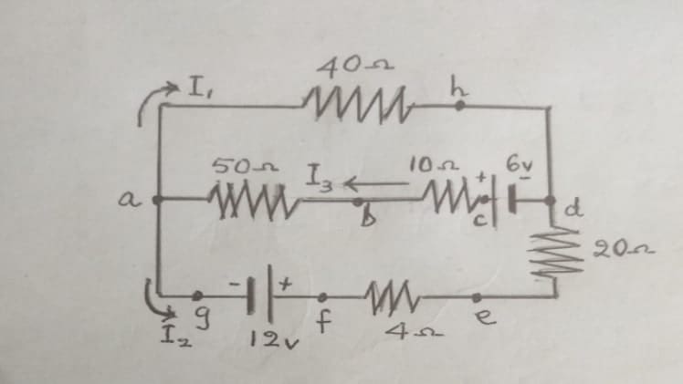
Let us use the given circuit to calculate the currents in the different loops.
Step 1: Label I1, I2, and I3.
Step 2: We need 3 equations for our 3 unknowns I1, I2, and I3.
Step 3: Applying Kirchoff’s Electric Circuit Law – Junction Rule, we have I3 = I1 + I2 —— (1)
Step 4: [a] Applying Kirchhoff’s Electric Circuit Law – Loop Rule to upper loop ‘ahdcba’, we have
Vha + Vdh + Vcd + Vbc + Vab = 0
We substitute values and signs and use Ohm’s Law equation V = RI
40 Ω (− I1 ) 0 ( 6 v) 10 Ω (− I3 ) 50 Ω (− I3 ) = 0
− 40 I1 6 – 60 I3 = 0
I3 = − 0,67 I1 0,1 ——————(2)
Step 5: [b] Applying Kirchhoff’s Electric Circuit Law – Loop Rule to big loop excluding the middle path ‘ahdefga’ we have
[we could use the lower loop too]
Vha + Vdh + Ved + Vfe + Vgf + Vag = 0
40 Ω (− I1) 0 20 Ω I2 4 Ω I2 (−12 v) 0 = 0
- 40 I1 + 24 I2 – 12 = 0
I2 = 1,67 I1 0,5 ——————–(3)
Step 6: Solve the algebraic equations.
From (1) I1 = I3 – I2
Substituting from (2) & (3)
I1 = − 0,67 I1 0,1 – [ 1,67 I1 0,5]
I1 = − 0,12 A
Using this value and substituting in equations (3) and (2) we get
I2 = 0,3 A and
I3 = 0,18 A
Which proves equation (1) to be true.
Conclusion
Some circuits are too complicated for such straightforward analyses. So, for complex circuits, we can use Kirchoff’s Electric Circuit Law. These were formulated by G R Kirchhoff (1824 – 1887) in the mid 19th century. There are two rules that he formulated.
Plagiarism Report